




01 · Overview
Charge-amplifier signal conditioning for piezoelectric measurement chains
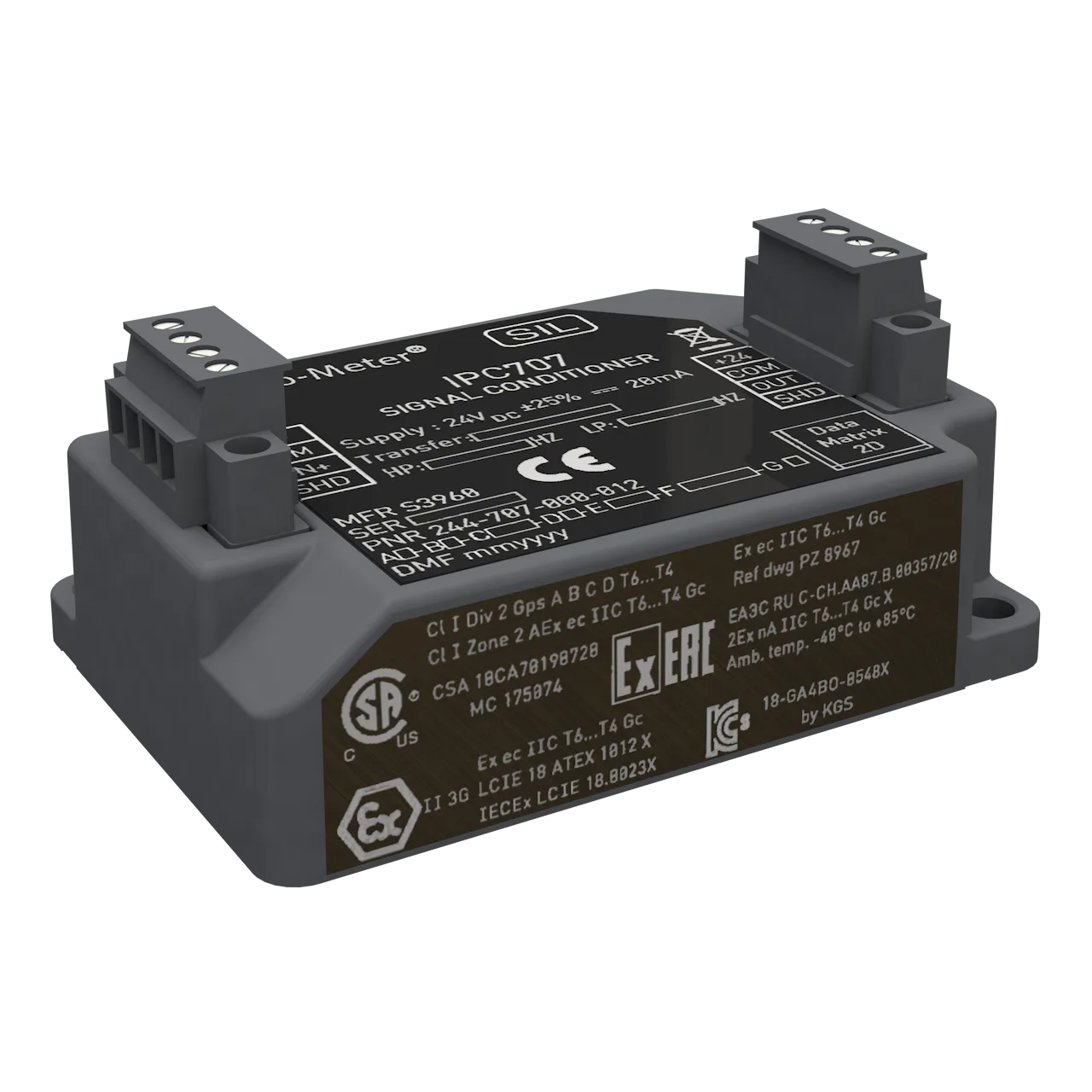
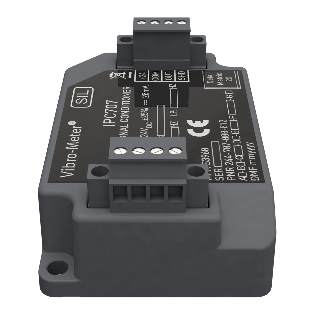
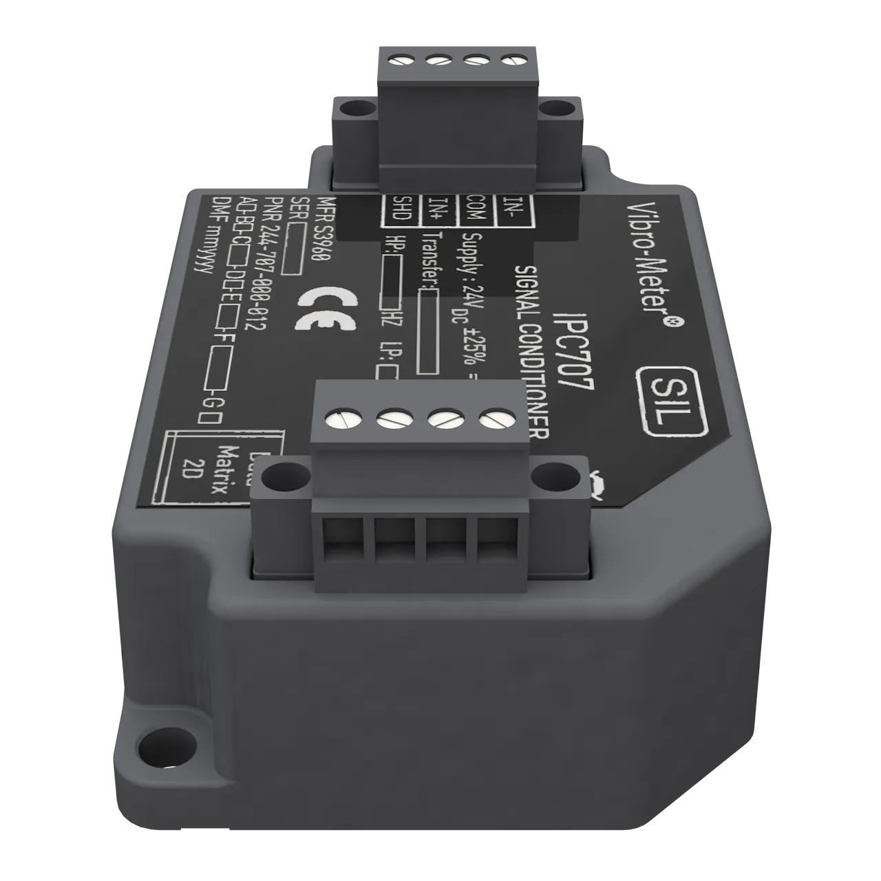
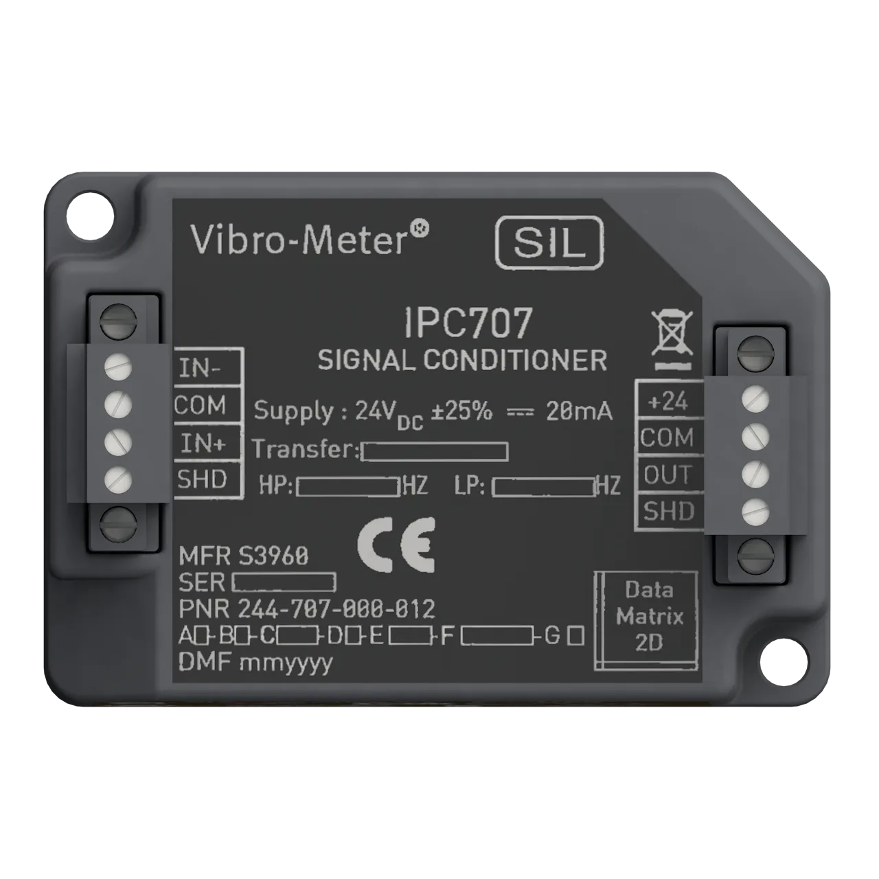
The IPC707 is a signal conditioner from Parker Meggitt's vibro-meter® product line, designed for operation with sensors that contain a piezoelectric sensing element and provide a charge output requiring an external charge amplifier.
It is a versatile and highly configurable device that converts the charge-based signal from a piezoelectric sensor into a current or voltage output, suitable for transmission to a monitoring system via a 2-wire (current) or 3-wire (voltage) cable.
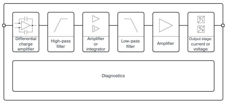
It includes RFI filters, optional hazardous-area protection, a differential charge amplifier, configurable HP/LP filters, an optional integrator (velocity output), and a configurable output stage. Optional diagnostic circuitry indicates measurement-chain problems remotely.
Replaces the previous IPC704 (form, fit and functionally equivalent). Use the interactive Configuration Wizard below the datasheet to size and order the right variant.
02 · Features & Benefits
Designed for precision, configured for your chain
For CAxxx accelerometers & CPxxx pressure sensors
From the vibro-meter® product line — works with any piezoelectric sensor with symmetrical (differential) signal output.
Configurable HP & LP filters
3rd order Butterworth high-pass and low-pass filters — independent of transfer function. Standard or non-standard cutoffs.
0.5 Hz to 50 kHz frequency range
Wide configurable bandwidth covering low-frequency processes through high-frequency vibration / pressure pulsations.
Optional velocity integrator
Internal integrator converts the acceleration signal into a velocity output — selectable via the D-code transfer-function option.
μA or mV output transfer
pC → μA for long-distance current-signal transmission, or pC → mV for shorter-distance voltage-signal transmission.
Ex versions for hazardous areas
Ex ia (Zones 0, 1, 2 — intrinsic safety) and Ex ec / nA (Zone 2 — increased safety) certified versions. ATEX, IECEx, cCSAus, KGS, UKEX, INMETRO, CCC, EAC.
SIL 2 / PL c Cat 1 capable
Suitable for functional-safety contexts per IEC 61508 (SIL 2) and ISO 13849 (PL c Cat 1). Optional diagnostic circuitry detects sensor / cabling / conditioner faults.
Removable screw-terminal connectors
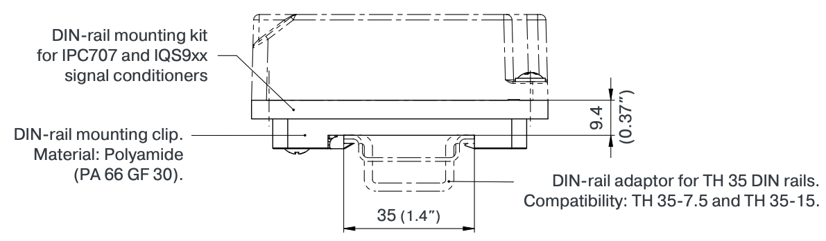
4 + 4 contact screw-terminal connectors. Optional MA130 DIN-rail mounting adaptor (TH 35).
Optional remote diagnostics
Optional diagnostic circuitry detects sensor, cabling and/or signal-conditioner problems — reported remotely via the DC level of the output signal.
03 · Specifications
Complete technical data
Block diagram
Environmental
| Operating and storage temperature | −40 to 85 °C (−40 to 185 °F) |
|---|---|
| Humidity | 95% max., non-condensing |
| Protection rating (IEC 60529) | IP40. Indoor use only unless installed in industrial housing/enclosure (≥ IP54). |
| Chemical resistance | Suitable for environments containing trace levels of chemicals such as hydrogen sulfide or ammonia |
| Flammability | UL94 V-0 |
| Vibration (IEC 60068-2-6) | 5 g peak above resonant frequency and 0.35 mm peak below (10 to 500 Hz, 6 hours/axis) |
| Shock acceleration (IEC 60068-2-27) | 15 g peak (half-sine, 11 ms duration, 9 shocks/axis) |
| Altitude | 4 000 m (13 100 ft) max. |
Power supply
| Input voltage range | 24 VDC ± 25% (18 to 30 VDC) |
|---|---|
| Current consumption (24 VDC nominal) | 20 mA max. |
Note: Power the IPC707 using a low-voltage supply such as a sensor power supply output from a VM600 or VibroSmart®, a GSI127 galvanic separator, or other suitable supply. In safety-related applications, use a supply with a safe limitation of 40 VDC.
Transfer function (option codes C and D)
| Transfer sensitivity | |
|---|---|
| Standard, without integrator | 0.1, 0.2, 0.5, 1, 2, 5, 10, 20 and 50 μA/pC or mV/pC |
| Standard, with integrator | 981, 1962, 4905, 9810, 19620, 49050 and 98100 μA/pC·s or mV/pC·s |
| Non-standard, without integrator | 0.1 to 110 μA/pC or mV/pC |
| Non-standard, with integrator | 981 to 98100 μA/pC·s or mV/pC·s |
| Accuracy (at ambient temperature) | |
| Without integrator | ± 2% |
| With integrator | ± 3% |
| Linearity error (INL) | < 0.2% |
| Temperature stability | Without int.: < 100 ppm/°C typical · With int.: < 150 ppm/°C typical |
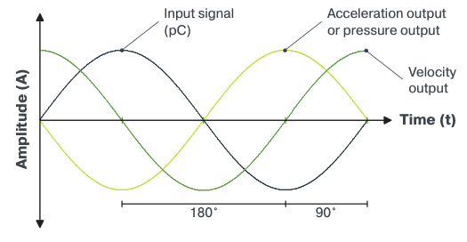
| Phase | Without int.: 180° between input and acceleration/pressure output. With int.: 270° between input and velocity output. |
Input characteristics
| RFI filter | Symmetrical LC network |
|---|---|
| Charge amplifier | Differential (symmetrical) |
| Dynamic range | |
| < 10 kHz | 50 000 pC |
| 10 to 50 kHz | 25 000 pC |
| Insulation resistance (sensor & cabling) | > 20 kΩ — minimum required by optional diagnostics |
| Capacitance (sensor & cabling) | < 15 nF — maximum allowed by optional diagnostics |
| Compatible sensors | Any piezoelectric-based sensor with symmetrical (differential) signal. CAxxx accelerometers and CPxxx pressure sensors are compatible. |
Output characteristics
Current output (2-wire transmission)
| Dynamic signal (AC) | ± 5 mA peak (max.) |
|---|---|
| Dynamic range (max.) | 5 mA peak / output sensitivity |
| Nominal output signal (DC) | |
| Without diagnostics | 12 mADC ± 0.2 mADC |
| With diagnostics | 13 mADC ± 0.2 (normal) · 11 mADC (sensor/cabling) · 10 mADC (signal conditioner) · < 8 mADC (other) |
| Output impedance | > 60 kΩ |
Voltage output (3-wire transmission)
| Dynamic signal (AC) | ± 5 V peak (max.) |
|---|---|
| Dynamic range (max.) | 5 V peak / output sensitivity |
| Nominal output signal (DC) | |
| Without diagnostics | 7.0 VDC ± 0.2 VDC |
| With diagnostics | 8.0 VDC ± 0.2 (normal) · 6.0 VDC (sensor/cabling) · 5.0 VDC (conditioner) · < 3.0 VDC (other) |
| Output impedance | < 500 Ω |
Filter characteristics
High-pass filter (option code E)
| Type | 3rd order Butterworth high-pass filter |
|---|---|
| Cutoff frequency (−3 dB) | |
| Standard, without diagnostics | 0.5, 1, 2, 5, 10 or 20 Hz |
| Standard, with diagnostics | 1, 2, 5, 10 or 20 Hz |
| Non-standard | 0.5 to 110 Hz (1 Hz min. with diagnostics) |
| Slope | −60 dB/decade (−18 dB/octave) min. |
Low-pass filter (option code F)
| Type | 3rd order Butterworth low-pass filter |
|---|---|
| Cutoff (standard) | 500, 1 000, 2 000, 5 000, 10 000, 20 000 or 50 000 Hz |
| Cutoff (non-standard) | 200 to 20 000 Hz |
| 50 000 Hz restrictions | Available only without diagnostics (option code B1) and without the integrator (transfer units D1 or D2 only — excludes D3/D4) |
| Slope | −60 dB/decade (−18 dB/octave) min. |
Connectors
| Screw-terminal connector (input) | 4 contacts for sensor-side signals |
|---|---|
| Screw-terminal connector (output) | 4 contacts for monitor-side signals |
| Electrical connections (IEC) | 320 V / 17.5 A / 0.2 to 1.5 mm² |
| Electrical connections (UL) | 300 V / 10 A / 28 to 16 AWG |
| Tightening torque | 0.2 to 0.25 N·m (0.15 to 0.18 lb-ft) |
Physical
| Housing material | Injection-moulded aluminium, painted |
|---|---|
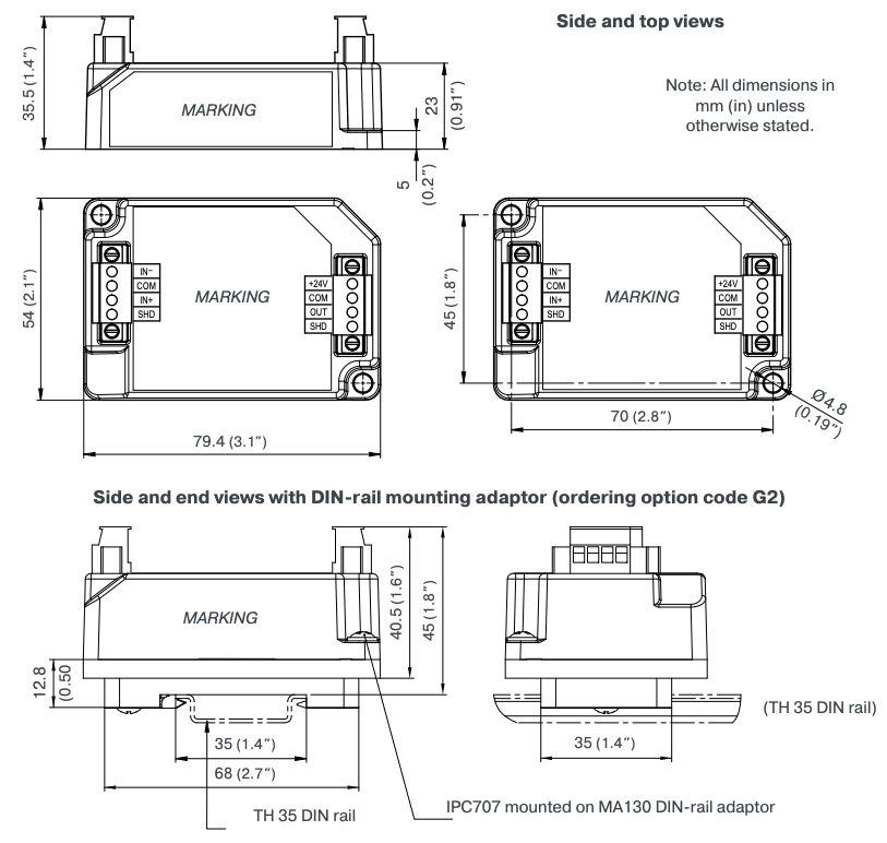
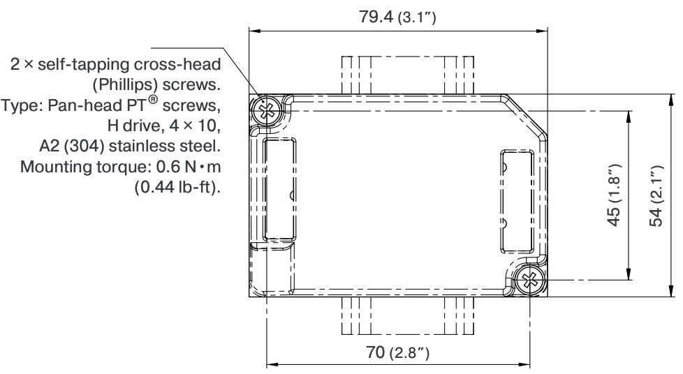
| Dimensions | 79.4 × 54 × 35.5 mm (3.1 × 2.1 × 1.4 in) |
| Weight | 175 g (0.39 lb) approx. |
| Mounting (without DIN-rail adaptor) | Two M4 screws |
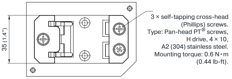
| Mounting (with MA130 DIN-rail adaptor, code G2) | TH 35 DIN rails (EN 50022 / IEC 60715) |
04 · Configure & Order
Configure & order your IPC707
Specify your sensor and desired output to compute the transfer-sensitivity C-code, snap to the nearest standard value, and assemble the complete IPC707 part number.
1Input (sensor)
2Output
3Filters
4Options
Note: C-code is computed from input/output sensitivities (max 4 sig digits, max 5 before decimal, 2 after). For non-standard E (HP) or F (LP) values use the Filters panel above with the "Custom…" option. Use each dropdown in the PNR sequence to set the corresponding code directly.
Visual position on the standard transfer-sensitivity chart
The orange marker indicates your current configuration on the standard sensitivity curves and updates automatically as you change inputs.
The IPC707 part number is composed of a fixed prefix and seven option codes (A — environment, B — diagnostics, C — transfer sensitivity, D — transfer units, E — high-pass cutoff, F — low-pass cutoff, G — installation).
05 · Mechanical
Mechanical drawings
 V012
V012 .step
.step
MA130 DIN-rail mounting adaptor
 V021.step
Note: All dimensions in mm (in) unless otherwise stated.
Ordering number (PNR): 809-130-000-021
06 · Approvals
Hazardous-area certifications & compliance
Available in Ex approved versions for use in hazardous areas.
Type of protection Ex ia — intrinsic safety (option code A2)
| Region | Certificate | Marking | Document |
|---|---|---|---|
| Europe | EU type examination · LCIE 18 ATEX 3026 X | II 1G (Zones 0, 1, 2) · Ex ia IIC T6…T4 Ga | EN/FR |
| International | IECEx · IECEx LCIE 18.0023X | Ex ia IIC T6…T4 Ga | EN |
| North America | cCSAus · 70198728 | Class I, Div. 1, Groups A, B, C, D · Ex ia IIC T6…T4 Ga Class I, Zone 0 · AEx ia IIC T6…T4 Ga | EN |
| South Korea | KGS* · KGS 18-GA4BO-0549X | Ex ia IIC T6…T4 | KO |
| United Kingdom | UK type examination* · CML 21 UKEX 2543 X | II 1G · Ex ia IIC T6…T4 Ga | EN |
| Kyrgyzstan (EAEU) | EAЭC KG certificate of conformity* · ЕАЭС KG417 039.CH.02.04445 | 0Ex ia IIC T6…T4 Ga | RU |
| Brazil | INMETRO* · INMETRO BVC20.3861-X | Ex ia IIC T6…T4 Ga | EN/PT-BR |
| China | CNEx CCC* · 2022312310000425 | Ex ia IIC T6/T5/T4 Ga | ZH |
Type of protection Ex ec / Ex nA — increased safety / non-sparking (option code A3)
| Region | Certificate | Marking | Document |
|---|---|---|---|
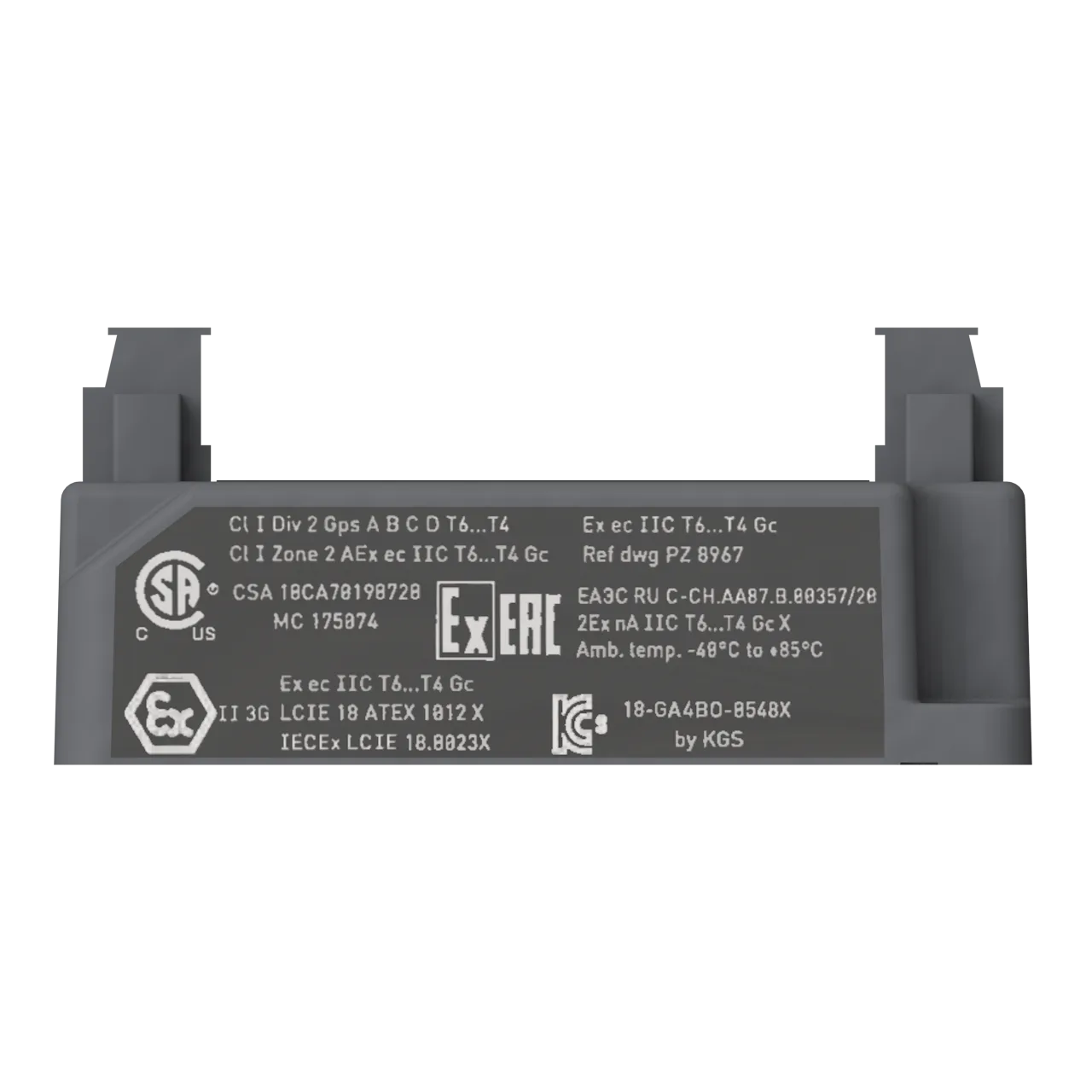
| Europe | Type examination · LCIE 18 ATEX 1012 X | II 3G (Zone 2) · Ex ec IIC T6…T4 Gc | EN/FR |
| International | IECEx · IECEx LCIE 18.0023X | Ex ec IIC T6…T4 Gc | EN |
| North America | cCSAus · 70198728 | Class I, Div. 2, Groups A, B, C, D · Ex ec IIC T6…T4 Gc Class I, Zone 2 · AEx ec IIC T6…T4 Gc | EN |
| South Korea | KGS · KGS 18-GA4BO-0548X | Ex nA IIC T6…T4 | KO |
| United Kingdom | UK type examination · CML 21 UKEX 4544 X | II 3G · Ex ec IIC T6…T4 Gc | EN |
| Kyrgyzstan (EAEU) | EAЭC KG certificate of conformity · ЕАЭС KG417 039.CH.02.04445 | 2Ex ec IIC T6…T4 Gc | RU |
| Brazil | INMETRO · INMETRO BVC20.3861-X | Ex ec IIC T6…T4 Gc | EN/PT-BR |
| China | CNEx CCC · 2022312310000425 | Ex ec IIC T6/T5/T4 Gc | ZH |
*Not engraved/marked on all versions of the product. When using Ex ec or Ex nA, install the IPC707 in a housing/enclosure with rating ≥ IP54.
General approvals
| Conformity | EU declaration of conformity (CE marking). UK (UKCA) declaration of conformity. |
|---|---|
| EMC | EMC compliant (2014/30/EU): EN 61000-6-2:2005 · EN 61326-1:2013 · EN 61326-3-2:2008 (SIL). |
| Electrical safety | EN 61010-1:2010 |
| Environmental management | RoHS compliant (2011/65/EU) |
| Hazardous areas | Ex approved versions (see above) |
| Functional safety | SIL 2 (IEC 61508). PL c Cat 1 (ISO 13849).SIL 2 · Z10-103309-0001EN |
07 · Accessories
Accessories & companions
ABA17x
Industrial housings
Industrial housings — refer to corresponding data sheet.
MA130
DIN-rail mounting adaptor
DIN-rail mounting adaptor for IPC707 (and IQS9xx) signal conditioners. Suitable for TH 35 DIN rails (EN 50022 / IEC 60715). PNR: 809-130-000-021.
GSI127
Galvanic separation unit
Galvanic separation unit — strongly recommended for installations affected by frame voltage. Always required when used with CPxxx pressure sensors.
Parker Hannifin Corporation – usually referred to as just Parker – is a global leader in motion and control technologies, providing precision-engineered solutions for a wide variety of mobile, industrial and aerospace markets. For more than a century the company has been enabling engineering breakthroughs that lead to a better tomorrow.
Parker Meggitt joined the Parker Aerospace Group in September 2022 following the successful acquisition of Meggitt PLC, a world leader in aerospace, defense and energy. This includes the Meggitt facility in Fribourg, Switzerland, operating as the legal entity Meggitt SA (formerly Vibro-Meter SA). Accordingly, the vibro-meter® product line is now owned by Parker.
All information in this document, such as descriptions, specifications, drawings, recommendations and other statements, is believed to be correct and reliable. Although given in good faith, the accuracy and/or completeness of such data is not guaranteed or legally binding on Parker Meggitt (Meggitt SA) and we reserve the right to alter any part of this document/publication without prior notice. Before acquiring and/or using this product, you should evaluate it and determine if it is suitable for your intended application. You should also check our website at www.meggittsensing.com/energy to ensure that the latest versions of documentation are being used. For example, data sheets, certificates, product drawings, user manuals, service bulletins and/or other instructions affecting the product.
Unless expressly agreed in writing with Parker Meggitt, you assume all risks and liability associated with use of the product. Any recommendations and advice given without charge, whilst given in good faith, are not legally binding. We take no responsibility for any statements related to the product which are not contained in a current Parker Meggitt publication, nor for any statements contained in extracts, summaries, translations or any other documents not authored and produced by us.
The certifications and warranties applicable to the products supplied by Parker Meggitt are valid only for new products purchased directly from us or an authorized distributor.
In this publication, a dot (.) is used as the decimal separator and thousands are separated by thin spaces. Example: 12345.67890.
Copyright © 2025 Parker Meggitt. All rights reserved.
Sales offices and distributors
Parker has sales offices and distributors all around the world. For information on your local contact, please visit our website.


Local representative
Parker Meggitt (Meggitt SA) office
Motion, Power & Sensing Division (MPSD)
Meggitt SA, Rte de Moncor 4, PO Box 1616, 1701 Fribourg, Switzerland
Tel: +41 26 407 11 11
www.meggittsensing.com/energy
www.meggitt.com
www.parker.com